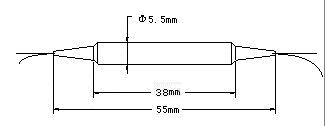

| Hybrid Isolator: Tap+1480/1550 WDM +Isolator | |
| Features | Applications |
|
|
|
Spec and Parameter |
| Parameter | Unit | Single stage | Dual stage | ||
| Signal Channel | Wavelength Range (¦Ës) |
dB |
1530-1565, 1570-1610 |
||
| Insertion loss(@¦Ës, All SOP) |
1% |
dB |
typ. 0.7 |
typ. 0.8 |
|
| 3% | dB | typ. 0.8 | typ. 0.9 | ||
| 5% | dB | typ.0.9 | typ.1.0 | ||
| Insertion loss(@¦Ës,0-70¡æ,All SOP) |
1% |
dB |
<0.9 | <1.0 | |
| 3% |
dB |
<1.0 | <1.1 | ||
| 5% | dB | <1.1 | <1.2 | ||
| Peak Isolation | dB |
40 |
50 |
||
| Isolation(@¦Ës,23¡æ,All SOP) |
Min |
dB |
30 |
44 |
|
| Channel Isolation(@¦Ëp,23¡æ,All SOP) |
Min |
dB |
55 | ||
| PDL | Max |
dB |
0.1 | ||
| PMD | Max |
ps |
0.1 | 0.05 | |
| Pump Channel | Wavelength Range (¦Ëp) |
dB |
1460-1500 | ||
| Insertion loss(@¦Ës, All SOP) |
Typ |
dB |
0.4 | ||
| Insertion loss(@¦Ëp,0-70¡æ,All SOP) |
Max |
dB |
0.6 | ||
| Channel Isolation(@¦Ës,23¡æ,All SOP) |
Min |
dB |
17 | ||
| PDL | Max |
dB |
0.1 | ||
| Tap port | Insertion Loss (@¦Ës,0-70¡æ,All SOP) | 1% |
dB |
19~21 | |
| 3% |
dB |
14~16 | |||
| 5% |
dB |
12~14 | |||
| Ripple | Max | dB | 0.2 | ||
| Directivit |
Min |
dB |
60 | ||
| Return loss | Min | dB | 55 | ||
| Optical power | Max | mW | 300 | ||
| Operation Temperature |
¡æ |
-20 to 70 |
|||
| Storage Temperature |
¡æ |
-40 to 85 |
|||
| * SOP=State Of Polarization |
| Pictures | |
|
|
|
 |
| Information of Order to Provide | ||||||
| TIWDM | Central wavelength | Stage | Tap ratio | Pigtail | Fiber length | Connector |
| 95=980/1550nm 99=980/1590nm 45=1480/1550nm 49=1480/1590nm xx=others |
D=Dual stage S=Single stage |
01=1% 02=2% 03=3% 05=5% xx=others |
B=250um
bare fiber L=900um |
10=1.0m |
NE=None FA=FC/APC FC=FC/PC SA=SC/APC SC=SC/PC ST=ST/PC LA=LC/APC LC=LC/PC XX=others |
|
|
|
| Home |
| Fiberer Global Tech Ltd. Copyright© e-mail:sales@Fiberer.com |
| professional optics communication equipment provider |
| provide optical fiber equipment | supply optics communication equipment |